

Literature
Tailor made solutions for customers and create more innovative products for them
Author: Dongguan DENSON Functional Materials Co., Ltd.
Epoxy resin cast dry-type transformers (Cast Resin Transformers, CRT) have become the preferred transformation equipment for urban distribution networks, data centers, rail transit, and renewable energy grid integration, thanks to their fire retardancy, maintenance-free operation, moisture and contamination resistance, and flexible installation. In 2026, China's resin-cast dry-type transformer market is expected to reach 13.79 billion RMB, with a year-on-year growth of 7.2%, of which epoxy-cast products account for over 86%.
However, the industry is undergoing a profound technological transformation. On one hand, GB 20052-2024 "Minimum Allowable Values of Energy Efficiency and Energy Efficiency Grades for Power Transformers" was officially implemented on February 1, 2025. The "Distribution Transformer Energy Efficiency Improvement Plan (2024–2027)" explicitly requires that all newly commissioned dry-type transformers from 2025 onward meet no less than SCB14 (Tier 2 energy efficiency). Combined with overseas energy efficiency regulations such as the EU EcoDesign Tier 3 Directive and the US DOE new regulations, the continuous rise in energy efficiency thresholds is reshaping the competitive landscape. On the other hand, downstream demands such as the construction of new power systems, large-scale renewable energy grid integration, and data center computing power expansion have imposed unprecedented requirements on transformer overload capability, intelligence level, and environmental adaptability.
This article systematically analyzes the future development directions and new technical requirements of epoxy resin cast dry-type transformers from six dimensions: energy efficiency improvement, material innovation, process upgrading, intelligent operation and maintenance, green and low-carbon transition, and application expansion.
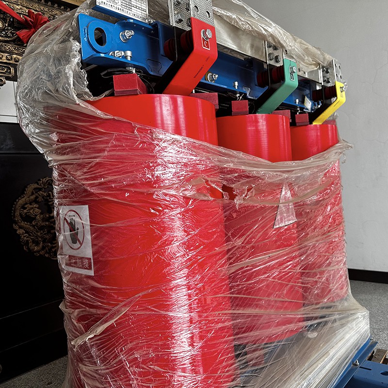
China's dry-type transformer energy efficiency grades have undergone continuous upgrades from SCB10 → SCB11 → SCB12 → SCB13 → SCB14 → SCB18. Following the implementation of GB 20052-2024, SCB14 (Tier 2 energy efficiency, NX2) has become the market access threshold, while SCB18 (Tier 1 energy efficiency, NX1) has become the mainstream in the high-end market. Taking a 1250 kVA product as an example:
| Performance Code | Energy Efficiency Grade | No-Load Loss (W) | Load Loss (W) | Energy Saving vs. SCB10 |
|---|---|---|---|---|
| SCB10 | Obsolete | ~420 | ~10,500 | Baseline |
| SCB13 | Tier 3 | ~340 | ~9,200 | No-load -19%, Load -12% |
| SCB14 | Tier 2 | ~280 | ~8,200 | No-load -33%, Load -22% |
| SCB18 | Tier 1 | ~200 | ~7,200 | No-load -52%, Load -31% |
The core breakthrough for energy efficiency improvement lies in the magnetic core material revolution. The iron loss of conventional grain-oriented silicon steel sheets (such as 30Q120) is approaching the physical limit of the material, leaving limited room for further reduction of no-load loss. Amorphous alloy strips, due to their long-range disordered atomic arrangement, exhibit extremely low hysteresis loss, and their no-load loss can be 60%–80% lower than that of silicon steel cores of the same capacity.
The SCBH15 series amorphous alloy dry-type transformers have achieved mass production, with the no-load loss of 1250 kVA products reduced to below 120 W. However, amorphous alloy materials present three major technical challenges:
Thin strip thickness (approximately 25 μm, only 1/10 of silicon steel sheet), resulting in a low stacking factor and a core fill factor reduction of approximately 5–8%;
Hard and brittle material, making shearing and stacking processes difficult and imposing extremely high requirements on core manufacturing equipment and process control;
High magnetostriction coefficient, resulting in no-load noise 3–5 dB higher than silicon steel cores, requiring optimized core structure and vibration damping design.
Future directions: The increasing domestic production rate of amorphous alloy strips (domestically produced amorphous strips have now reached international quality levels, with costs approximately 20% lower than imports), core structure optimization (stepped lap joints, rectangular cross-section optimization), and integrated sound insulation and noise reduction design will drive the penetration rate of amorphous dry-type transformers in the Tier 1 energy efficiency market from the current approximately 15% to over 40% by 2030.
The reduction of load loss (copper loss) is mainly achieved through the following approaches:
Conductor material upgrading: High-purity copper (oxygen content ≤0.001%) replacing conventional copper, reducing resistivity by approximately 1–2%;
Winding structure optimization: Foil windings replacing wire-wound windings, with low-voltage windings using copper foil (thickness 0.5–2.0 mm), providing better axial heat dissipation and reducing eddy current loss by approximately 15%;
Transposed conductor application: High-voltage windings using continuously transposed conductors (CTC), reducing additional losses caused by skin effect and proximity effect;
Electromagnetic simulation-driven design: Optimizing winding turns, wire diameter, and arrangement based on finite element analysis (FEA), minimizing copper loss while meeting impedance voltage and short-circuit impedance requirements.
Epoxy resin is the core insulating material for cast dry-type transformers, and its performance directly determines the dielectric strength, thermal class, heat dissipation capability, and service life of the product. Currently, epoxy systems are undergoing multi-dimensional upgrading from conventional bisphenol-A systems toward high thermal conductivity, high heat resistance, low shrinkage, and environmental friendliness.
Conventional epoxy resins have a thermal conductivity of only approximately 0.2 W/(m·K), making them typical thermal insulators. Heat generated during winding operation must be conducted through the epoxy layer to the surface and then carried away by air. Insufficient thermal conductivity leads to high winding hot-spot temperatures, limiting the overload capability and power density of transformers.
High thermal conductivity epoxy systems construct continuous thermal conduction networks in the resin matrix by adding high thermal conductivity insulating fillers. The main technical routes include:
(1) Nano-SiO₂ Modified Systems
Using surface-modified nano-silica particles (particle size 10–50 nm), interfacial bonding with the epoxy matrix is improved through silane coupling agents (such as KH550). Nanoparticles form "thermal conduction network chains" in the system, increasing thermal conductivity to 1.5–1.8 W/(m·K), approximately 23% higher than conventional systems. In 2025, the shipment share of new resins using SiO₂ nano-modification had already reached 23.7%.
(2) Hexagonal Boron Nitride (h-BN) Filled Systems
h-BN has a graphene-like layered structure, with in-plane thermal conductivity as high as approximately 300 W/(m·K) and intrinsic electrical insulation. Adopting a synergistic filling strategy of "micron h-BN backbone + nano n-BN bridging," micron platelets establish the main heat dissipation path, while nanoparticles fill gaps and reduce interfacial contact thermal resistance, achieving thermal conductivity of 0.6–0.8 W/(m·K), an increase of over 200% compared to pure epoxy. The advantage of h-BN systems is their relatively small impact on epoxy viscosity, resulting in good casting processability.
(3) Alumina (Al₂O₃)/Metal Hybrid Systems
Using Al₂O₃-SnBi hybrid fillers, thermal conductivity can reach 2.95 W/(m·K) at a filler volume content of 60%. However, this system has high viscosity and difficult casting, and is currently mainly used in special scenarios such as solid-state transformer (SST) power module potting.
Engineering Value of High Thermal Conductivity Epoxy: Taking a 2000 kVA dry-type transformer as an example, after adopting high thermal conductivity epoxy with a thermal conductivity of 1.8 W/(m·K), the winding hot-spot temperature rise can be reduced by approximately 15–20 K. Under Class F insulation (maximum temperature rise 100 K), this enables an approximately 20% improvement in overload capability, or increases product power density by approximately 15% at the same temperature rise, achieving miniaturization and weight reduction.
Conventional cast dry-type transformers mostly use Class F insulation (maximum operating temperature 155°C, temperature rise limit 100 K). With increasing requirements for overload capability and compactness in scenarios such as data centers and renewable energy grid integration, Class H insulation systems (maximum operating temperature 180°C, temperature rise limit 125 K) are accelerating in popularity. Between 2023 and 2025, approximately 38% of newly introduced cast dry-type transformer models adopted Class H insulation systems, enabling continuous operation at temperatures up to 180°C and improving overload tolerance by approximately 15%.
Key technologies for Class H epoxy systems:
Cycloaliphatic epoxy resins: Replacing bisphenol-A benzene ring structures with cycloaliphatic structures, increasing heat deflection temperature (HDT) to above 155°C, with excellent UV resistance and weatherability, suitable for outdoor and high-temperature environments;
Anhydride curing agent optimization: Using high-temperature resistant curing agents such as methyl nadic anhydride (MNA) and hexahydrophthalic anhydride (HHPA), with accelerators to precisely control the curing reaction rate;
Glass transition temperature (Tg) improvement: Class H systems require Tg above 170°C, ensuring sufficient mechanical strength and insulation performance at maximum operating temperatures.
The volume shrinkage rate of epoxy resins during curing is approximately 2–5%, and the internal stress generated by shrinkage may lead to winding conductor displacement, insulation layer cracking, and reduced partial discharge inception voltage. Large-capacity, high-voltage grade products have particularly urgent requirements for low-shrinkage epoxy.
Technical directions:
Reactive diluent optimization: Using low-viscosity reactive diluents such as butyl glycidyl ether (501) and 1,4-butanediol diglycidyl ether (622), reducing system viscosity while minimizing curing shrinkage;
Toughening modification: Introducing toughening agents such as carboxyl-terminated butadiene-acrylonitrile rubber (CTBN) and core-shell rubber (CSR), improving epoxy fracture toughness and absorbing curing shrinkage stress;
Inorganic filler grading: Using graded fillers of different particle sizes (such as micron SiO₂ + nano SiO₂), increasing filler packing density and reducing the resin phase proportion, thereby lowering overall shrinkage.
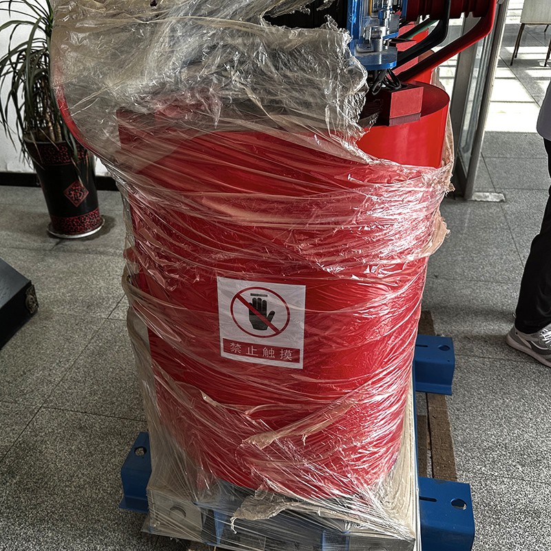
As epoxy matrices evolve toward high thermal conductivity, high heat resistance, and low viscosity, supporting auxiliary materials such as color pastes must also be upgraded synchronously. High thermal conductivity epoxy systems have high filler content and high system viscosity, making it difficult for conventional color pastes to disperse uniformly, which can easily lead to color spots, color differences, and local agglomeration. Specialized color pastes with low viscosity, high dispersibility, and easy dissolution (such as the EP-988 epoxy special black paste) have become the ideal supporting solution for high thermal conductivity, high-gloss epoxy systems — their low viscosity characteristic does not further increase system viscosity, high dispersibility ensures uniform coloring even in high-filler systems, and easy dissolution guarantees compatibility with various epoxy matrices (including cycloaliphatic systems) without affecting insulation performance or curing reactions.
The core process of epoxy resin casting is vacuum pressure casting — injecting defoamed epoxy mixture into preheated molds under vacuum environment (vacuum degree ≤100 Pa), ensuring no bubbles or pores in the winding insulation layer. Conventional processes rely on manual experience to control casting speed, vacuum degree, and temperature, with a yield rate of approximately 92%.
Intelligent upgrading directions:
Fully automatic vacuum casting production lines: Integrating full-process automation including automatic batching (accuracy ±0.1%), vacuum defoaming, mold preheating, robotic casting, and curing oven temperature control, increasing yield rate to over 99%;
Online viscosity monitoring: Using vibrating or rotational online viscometers to monitor mixture viscosity in real time, dynamically adjusting casting speed and mold temperature;
Vacuum degree closed-loop control: PID closed-loop control of vacuum degree with accuracy ±5 Pa, ensuring consistent defoaming效果;
Multi-layer winding stress simulation modeling: Predicting temperature and stress fields during curing through finite element simulation, optimizing curing curves (heating rate, holding time, cooling rate), and reducing the risk of curing cracking.
The vacuum pressure impregnation (VPI) process has traditionally been used for winding insulation treatment of oil-immersed and open-type dry-type transformers, while the casting process uses overall mold encapsulation. The two processes are converging:
Pre-impregnation + casting composite process: Windings are first pre-impregnated with insulating varnish via VPI, then subjected to epoxy casting, improving the internal insulation compactness of windings and reducing partial discharge;
Precise gel time control: Precisely controlling epoxy gel time (typically 15–30 minutes) through accelerator dosage and curing temperature, ensuring the mixture fully fills winding gaps before gelation.
High-precision molds: Using CNC-machined steel molds with cavity dimensional accuracy ±0.05 mm and surface roughness Ra ≤0.4 μm, ensuring the appearance quality of cast bodies;
Release agent upgrading: Using fluorine-based or silicone semi-permanent release agents, with one coating reusable for 5–10 times, reducing the impact of release agent residue on surface quality;
Flexible mold technology: For irregular windings and large-capacity products, using silicone flexible molds to reduce demolding difficulty and minimize demolding damage.
In 2025, approximately 92.4% of newly delivered dry-type transformers were already equipped with built-in fiber optic temperature sensors and partial discharge monitoring devices. Intelligent sensing systems are transitioning from "optional configuration" to "standard configuration."
(1) Direct Winding Hot-Spot Temperature Measurement
Conventional Pt100 temperature measurement can only be installed on the winding surface, measuring ambient temperature rather than the true hot-spot temperature, with errors of up to 10–15°C. Fluorescent fiber optic temperature measurement and fiber Bragg grating (FBG) temperature measurement technologies allow fiber optic probes to be directly embedded inside high-voltage windings, achieving:
Direct measurement of the true winding hot-spot temperature with accuracy ±1°C;
Complete electromagnetic interference immunity (EMC Class 4), withstanding high voltages above 35 kV;
Multi-point distributed temperature measurement, with 3–5 measurement points arranged along the winding axial direction, real-time monitoring of temperature distribution.
(2) Online Partial Discharge Monitoring
Partial discharge is an early sign of epoxy insulation degradation. Using ultra-high frequency (UHF) sensors (detection frequency band 300 MHz–1.5 GHz), designed as ring structures embedded in the end shielding layer of the cast body, effectively avoiding external electromagnetic noise interference, and capable of identifying pico-Coulomb (pC) level weak discharge signals. Combined with high-frequency current transformers (HFCT) and ultrasonic detection, multi-dimensional comprehensive localization of partial discharge is achieved, with localization accuracy up to 20 cm.
(3) Core Grounding Current Monitoring
Real-time monitoring of core grounding current (normally ≤0.1 A), providing early warning of faults such as core multi-point grounding and poor insulation of through-core bolts, preventing local core overheating.
(4) Vibration and Acoustic Monitoring
Installing vibration sensors on core clamps and windings to monitor core magnetostriction vibration and winding electromagnetic force vibration, identifying mechanical faults such as core loosening and winding deformation through vibration spectrum analysis.
Intelligent dry-type transformers adopt a "device-edge-cloud" three-tier data architecture:
Device layer: Various sensors collect data such as temperature, partial discharge, current, and vibration, with sampling frequencies ranging from 1 Hz (temperature) to 10 MHz (partial discharge);
Edge layer: Embedded AI chips (such as ARM Cortex-A series + NPU) perform local data preprocessing, feature extraction, and fault diagnosis, with response time <100 ms, reducing cloud communication pressure;
Cloud layer: Big data analytics platforms aggregate data from multiple devices, performing trend analysis, life prediction, and energy efficiency optimization, supporting remote monitoring via Web and mobile terminals.
Based on equipment 3D models and real-time operational data, a transformer digital twin is constructed:
Simulating temperature and electric field distributions under different loads and environmental conditions;
Predicting insulation aging trends and remaining useful life (RUL);
Optimizing maintenance plans, transitioning from "scheduled maintenance" to "condition-based maintenance";
Fault simulation and early warning, enabling proactive intervention before faults occur.
All 126 intelligent dry-type transformers delivered to the Shenzhen Qianhai Shenzhen-Hong Kong Modern Service Industry Cooperation Zone in 2025 are equipped with digital twin systems, achieving full lifecycle condition management.
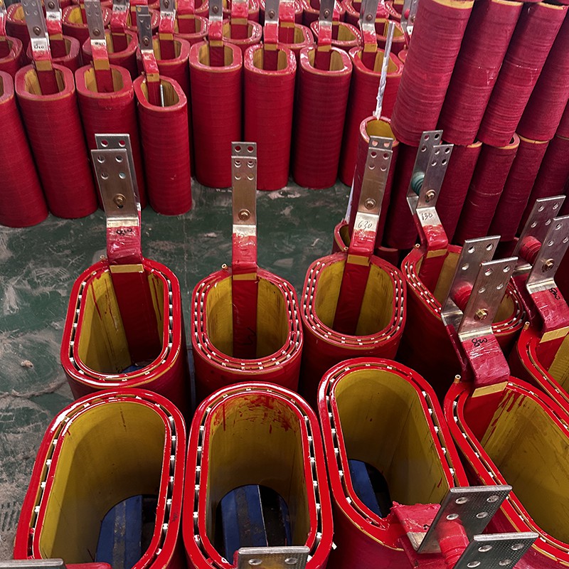
Conventional bisphenol-A epoxy resins are not only listed in the EU REACH SVHC candidate list due to containing endocrine-disrupting compounds (bisphenol A), but their petrochemical raw material sources also result in high full-lifecycle carbon emissions. The industry is accelerating the transition to bio-based epoxy systems:
Cardanol-modified epoxy: Using cardanol extracted from cashew nut shell liquid as a raw material to partially replace bisphenol A, reducing carbon footprint by 35%–50%. The long alkyl chain in the cardanol structure also imparts excellent toughness and water resistance to the epoxy;
Rosin derivative epoxy: Prepared from rosin acid, which is a pine tree secretion and a renewable source, and has already achieved industrial production;
Lignin-based epoxy: Using enzymatic lignin from straw as raw material, domestic enterprises have achieved mass production, with products obtaining carbon footprint and ISCC certification, applicable to various processes such as winding, pultrusion, and casting;
Vanillin-based degradable epoxy: Using vanillin (extractable from lignin) as raw material, introducing dynamic imine bonds to prepare degradable epoxy glassy materials. After curing, they can be completely depolymerized into vanillin and polyols under specific conditions, enabling closed-loop recycling.
Epoxy resins form permanent three-dimensional cross-linked networks after curing, and conventionally, the epoxy cast bodies of retired transformers can only be landfilled or incinerated, resulting in serious resource waste. Recyclable epoxy technology is making breakthroughs:
Dynamic covalent bond networks: Introducing dynamic covalent bonds such as imine bonds, disulfide bonds, and Diels-Alder bonds, enabling epoxy to undergo bond exchange reactions under specific conditions (heating, catalysts, specific solvents), achieving remoldability and degradability;
Physical recycling: Crushing retired cast bodies and using them as fillers in new epoxy systems, achieving partial material circulation;
Chemical depolymerization: Breaking epoxy cross-linked networks under high temperature and pressure or in specific solvents, recovering polyols and amine raw materials.
China has developed the world's first 35 kV degradable epoxy resin cast dry-type transformer, with the epoxy body completely degradable within 24 hours under specific conditions, paving the way for closed-loop resource utilization.
According to calculations by the China Electric Power Research Institute, a 2000 kVA epoxy resin dry-type transformer has a carbon footprint of approximately 128 tons of CO₂ equivalent over its 30-year service life, approximately 34 tons less than an oil-immersed transformer of the same specification. The carbon footprint composition is approximately:
Raw material production (copper, silicon steel, epoxy): approximately 45%;
Manufacturing process (energy consumption, emissions): approximately 10%;
Operation phase (loss power consumption): approximately 40%;
Retirement and disposal: approximately 5%.
Future carbon footprint management directions:
Low-carbon raw materials: Recycled copper windings (some enterprises reduce copper loss per unit product by 0.8 W/kVA, annually reducing primary copper mining by over 6,000 tons), low-carbon silicon steel, bio-based epoxy;
Green manufacturing: Factory use of green electricity, low-VOC resins, closed-loop solvent recovery;
Efficient operation: Tier 1 energy efficiency products can reduce carbon emissions by approximately 20–30 tons through electricity savings over 30 years of operation;
End-of-life resource recovery: Recyclable epoxy, high-value recovery of copper and silicon steel.
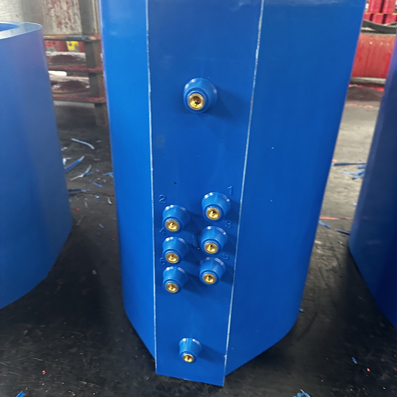
In photovoltaic power station step-up stations and wind farm pad-mounted transformers, the proportion of resin-cast transformers is expected to increase from 41.2% in 2025 to 44.7% in 2026. Renewable energy scenarios impose new requirements on transformers:
Bidirectional power flow adaptability: Distributed photovoltaics and energy storage systems involve bidirectional power flow, and transformers must withstand voltage regulation and thermal stress under reverse power flow;
High overload capability: Renewable energy output fluctuates significantly, and transformers require short-time overload capability (120%–150% rated capacity for 1–2 hours), with high thermal conductivity epoxy and Class H insulation as key supporting technologies;
Outdoor weatherability: Offshore wind power and desert photovoltaic scenarios require epoxy systems with UV resistance, salt spray resistance, and high/low temperature cycle resistance, with cycloaliphatic epoxy systems having greater advantages.
Data center transformers require year-round uninterrupted operation with extremely high reliability requirements:
N+1 redundant configuration: Multiple transformers operating in parallel, with single-unit failure not affecting power supply;
High energy efficiency: Data center PUE (Power Usage Effectiveness) requirements ≤1.3, and transformer losses directly affect PUE, making Tier 1 energy efficiency (SCB18) standard;
Low noise: Data center机房 noise requirements ≤55 dB, requiring optimized core structure and vibration damping design, with the noise issue of amorphous alloy cores requiring special attention;
Intelligent monitoring: Integration with data center infrastructure management (DCIM) systems, enabling real-time monitoring and optimization of temperature, load, and energy efficiency.
Rail transit: On-board transformers and traction substation transformers require vibration resistance, impact resistance, small volume, and light weight, with the mechanical strength advantages of epoxy casting being prominent;
Offshore wind power: Offshore platform transformers require salt spray resistance (salt spray test ≥1000 h), high humidity resistance, and corrosion protection, with the sealing and corrosion resistance of epoxy cast bodies superior to oil-immersed transformers;
High altitude: In areas above 4000 m altitude, thin air results in poor heat dissipation and reduced external insulation strength, requiring optimized insulation distances and heat dissipation designs.
Solid-state transformers (also known as power electronic transformers) achieve voltage transformation, power quality management, and power flow control through AC-DC-AC conversion, and are core equipment for future smart distribution networks. The power modules (IGBT/SiC modules) of SST require epoxy resin potting insulation, imposing new requirements on epoxy systems:
High thermal conductivity: Power modules have high heat flux density (up to 100 W/cm²), requiring potting epoxy thermal conductivity ≥1.5 W/(m·K);
Low dielectric loss: Low dielectric loss at high frequencies (kHz–MHz level), avoiding dielectric heating;
Low partial discharge: High partial discharge inception voltage under high-frequency voltage, requiring strict control of potting bubbles;
SiC device compatibility: High temperature resistance (≥180°C), matching the operating temperature of SiC power devices.
Material cost pressure: New materials such as high thermal conductivity fillers, amorphous alloy strips, and bio-based epoxy still have higher costs than conventional materials. The initial investment for Tier 1 energy efficiency products is approximately 15%–25% higher than Tier 3, requiring total cost of ownership (TCO) analysis to persuade customers;
Standards lagging behind technology: Standard systems for new technologies such as intelligent dry-type transformers, recyclable epoxy, and Class H insulation are not yet fully developed. Group standards such as T/CEEIA 586-2022 "Technical Specification for Intelligent Dry-Type Transformers" are leading the way, and national standard revision needs to be accelerated;
Talent and process accumulation: New technologies such as fully automatic casting production lines, digital twins, and AI diagnostics significantly increase the capability requirements for engineers and skilled workers, with a clear industry talent gap;
Data security and interoperability: Intelligent devices generate large amounts of operational data, and issues such as data ownership, security protection, and protocol standardization (currently Modbus, IEC 61850, MQTT and other protocols coexist) urgently need to be resolved.
Based on the above analysis, it is expected that by 2030, epoxy resin cast dry-type transformers will exhibit the following technical characteristics:
| Technical Dimension | 2025 Status | 2030 Outlook |
|---|---|---|
| Energy Efficiency | SCB14 dominant, SCB18 high-end penetration | SCB18 widespread, super Tier 1 (SCB20+) mass production |
| Core Material | Grain-oriented silicon steel dominant, amorphous ~15% | Amorphous ~40%, high magnetic induction silicon steel widespread |
| Epoxy System | Bisphenol-A dominant, nano-modification penetration | High thermal conductivity (≥1.5 W/m·K) + Class H mainstream, bio-based ~20% |
| Insulation Class | Class F dominant, Class H penetration | Class H widespread, Class C (220°C) R&D |
| Intelligence | Fiber optic temp + PD monitoring standard | Digital twin + AI predictive maintenance widespread, device-edge-cloud collaboration |
| Green & Low-Carbon | Carbon footprint concept introduced | Full lifecycle carbon footprint certification mandatory, recyclable epoxy mass production |
| Power Density | Conventional design | High thermal conductivity + optimized design, power density +20%+ |
| Applications | Distribution dominant | Renewable energy, data centers, rail transit, SST multi-scenario expansion |
Epoxy resin cast dry-type transformers are in a critical period of transition from "traditional manufacturing" to "intelligent manufacturing + green and low-carbon." Energy efficiency improvement is the rigid driving force, material innovation (high thermal conductivity, high heat resistance, bio-based, recyclable) is the technical foundation, process upgrading (fully automatic casting, simulation-driven design) is the quality guarantee, intelligent operation and maintenance (embedded sensing, digital twins, AI diagnostics) is the value extension, and green and low-carbon (full lifecycle carbon footprint management, closed-loop recycling) is the long-term direction.
For transformer manufacturing enterprises, future competition will no longer be price competition for single products, but comprehensive capability competition of material systems + process capabilities + intelligent operation and maintenance + green certification. Enterprises that proactively deploy high thermal conductivity epoxy systems, amorphous alloy cores, intelligent sensing integration, and carbon footprint management will occupy an advantageous position in the new round of technological change.
For upstream material suppliers (including epoxy resins, curing agents, fillers, color pastes, etc.), it is essential to closely follow the technological upgrading pace of transformer OEMs and develop high-performance materials to match them — specialized color pastes with low viscosity, high dispersibility, and compatibility with various new epoxy systems, high thermal conductivity insulating fillers, bio-based epoxy monomers, etc., will all gain growth opportunities in the future market.
Keywords: Epoxy resin cast dry-type transformer, energy efficiency improvement, amorphous alloy, high thermal conductivity epoxy, nano-modification, Class H insulation, intelligent operation and maintenance, fiber optic temperature measurement, partial discharge, digital twin, bio-based epoxy, recyclable, carbon footprint, new power systemSource: Dongguan DENSON Functional Materials Co., Ltd.

Mr. Jia: 159-1691-0100 13360650502 Mr. Jiang:13924940045
Email:denson168@163.com
Address: Room 101, No. 1, Lane 11, Changsheng Street, Dalian Tang, Wanjiang Street, Dongguan City, Guangdong Province

备案号:粤ICP备19036602号 粤公网安备 44190002005999号 Copyright Dongguan DENSON New Materials Co., Ltd
